How to Calculate Linear Actuator Force
OEM method to calculate electric linear actuator force—static load, friction, angle, dynamics and safety factor—mapped to Elerover force classes and series.
· Elerover manufacturer guide
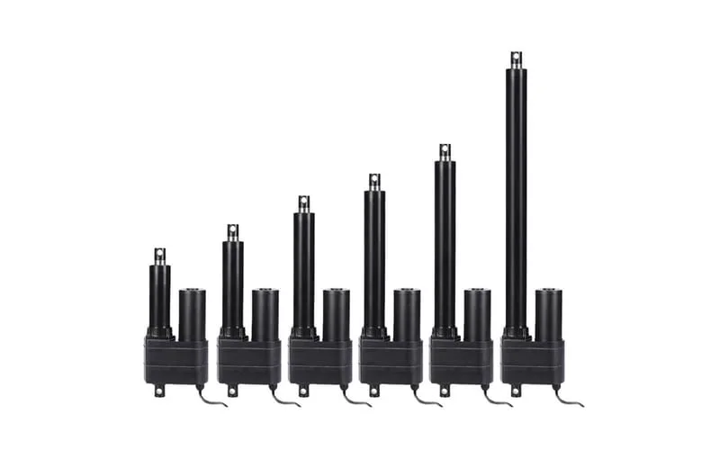
Correct force sizing is the difference between a reliable OEM motion system and a field full of stalled, overheated actuators. Elerover publishes Max Load (push/pull capacity) on each product page. Your job as a buyer or design engineer is to estimate the real axial demand—including friction, geometry and dynamics—before you pick a series.
This guide gives a practical calculation method used in B2B actuator selection, then maps results to Elerover force classes under the Linear Actuator category. It complements How to choose a linear actuator and the heavy-duty guide.
What “force” means on an actuator datasheet
Max Load is the axial push (and often pull) capacity the actuator can deliver under rated conditions. It is not:
- The weight of your product alone (unless the motion is a pure vertical lift with no friction)
- A side-load rating
- A guarantee at any voltage outside Working Voltage
- A continuous rating if duty cycle is exceeded
Always read Max Load together with Working Voltage, Protection Class and duty notes on the same product page.
Basic force estimate
Step 1 — Static weight component
For a vertical lift of mass m (kg):
F_static ≈ m × 9.8 N
Example: 200 kg → about 1,960 N before friction and safety factor.
Step 2 — Friction and mechanism losses
Add seal friction, hinge friction, guide friction and cable-drag allowances. If you lack measured data, apply a conservative percentage based on mechanism quality—or measure peak current on a prototype and back-calculate.
Step 3 — Angle and leverage
For hinged lids, ramps and links, the actuator rarely sees the full weight as pure axial load. Resolve forces along the actuator axis at the worst-case position. Many lids are hardest to open near closed position.
Step 4 — Dynamics
If the cycle accelerates quickly, add an inertial term. Aggressive indexing or emergency moves need more force than slow creep.
Step 5 — Safety factor
F_required ≈ (F_static_axial + F_friction + F_dynamic) × SF
Common SF: 1.5–2.0, higher for shock, ice, wind or uncertain friction.
Selection criteria after you have F_required
- Shortlist series whose Max Load exceeds F_required with margin.
- Confirm stroke and retracted length fit the envelope.
- Confirm voltage and cable design (12V vs 24V).
- Confirm IP rating for the environment (IP65 vs IP68).
- Confirm duty cycle is realistic for the force class.
- Open the product page and verify the exact Max Load for that stroke model.
Force class map (Elerover starting points)
| F_required (approx.) | Start here | Notes |
|---|---|---|
| Under ~200–300 N | SLA-T01 series | Compact furniture / light OEM |
| ~1–6 kN | SLA03 6000N or SLA01 | Gates, mid industrial |
| ~6–8 kN | SLA08 8000N | Lifts, construction, solar assists |
| ~8–12 kN | SLA-12K 12000N | Heavy hatches, outdoor industrial |
| Above practical screw range | Electric hydraulic actuators | Compare published load ratings |
Comparison table: what people forget to include
| Term | Often forgotten? | Effect if ignored |
|---|---|---|
| Hinge angle peak | Yes | Undercount near open/close |
| Guide friction | Yes | Chronic overheating |
| Ice / debris / wind | Yes (outdoor) | Seasonal stall failures |
| Acceleration | Sometimes | Stall on fast cycles |
| Side load from misalignment | Yes | Seal wear, reduced life |
| Safety factor | Sometimes | No margin for real world |
Engineering examples
Example A — Vertical platform, clean guides
- Mass: 350 kg
- F_static ≈ 3,430 N
- Friction allowance: 15% → ~515 N
- Dynamics small (slow move) → ~200 N
- SF = 1.5
F_required ≈ (3430 + 515 + 200) × 1.5 ≈ 6,220 N
Path: Linear Actuator → SLA08 8000N → e.g. SLA08 100mm construction model (confirm stroke and Max Load on page).
Example B — Hinged equipment cover
- Cover weight: 80 kg
- Worst-case axial share near closed: equivalent ~1,200 N (from linkage study)
- Wind/ice contingency: +400 N
- SF = 2.0 (outdoor uncertainty)
F_required ≈ (1200 + 400) × 2.0 = 3,200 N
Path: Category → SLA03 6000N → SLA03 gate latch / mid-force model or another stroke in the same series with adequate Max Load.
Example C — Heavy hatch ~1,000 kg class with leverage
- Effective axial demand from CAD: ~7,500 N at worst angle
- Friction + seal: +800 N
- SF = 1.5
F_required ≈ (7500 + 800) × 1.5 ≈ 12,450 N
Path: Category → SLA-12K → SLA-12K heavy-duty actuator. If duty is extreme or force climbs further, evaluate electric hydraulic options.
Example D — Compact furniture / robot mechanism
- Effective load: ~120 N with friction
- SF = 1.5 → ~180 N
Path: Category → SLA-T01 → compact models such as the T01 robot/OEM listing. Force is rarely the only constraint—noise, sync and stroke usually dominate.
Side load and mounting (force you cannot “buy away”)
Linear actuators are strongest along the rod axis. Side load from skewed mounts, long unsupported strokes or racking frames reduces capacity and damages seals. Before you jump two force classes:
- Fix mount coaxiality
- Add guides for the moving load
- Recalculate axial demand
- Then select Max Load
A larger actuator on a misaligned mount still fails early.
Applications and typical force drivers
| Application | Force drivers | Notes |
|---|---|---|
| Medical beds | Patient load + mechanism friction | Smooth duty; confirm SF with risk analysis |
| Recliners / desks | Low force, sync | Force usually secondary to noise/control |
| Agriculture covers | Wind, dust seals, ice | Outdoor IP + higher SF |
| Solar tracker assists | Panel load + wind | Long strokes; verify model Max Load |
| Vehicle hatches | Weight + road shock | Often SLA-12K class |
| Industrial fixtures | Clamping / positioning peaks | Check duty cycle carefully |
Recommended Elerover product path
- Calculate F_required with worst-case geometry
- Category: Linear Actuator
- Series: map to SLA-T01 / SLA03 / SLA08 / SLA-12K (or tubular if envelope/IP dominate)
- Products: verify Max Load on the exact stroke SKU
- Contact: send free-body diagram or CAD snapshot via Contact
Manufacturer review matters when leverage is complex. Elerover will map your F_required to a published series without inventing ratings beyond the catalog.
Converting units without mistakes
OEM drawings mix units. Keep one system in the calculation sheet:
| From | To newtons (approx.) |
|---|---|
| 1 kgf | 9.80665 N |
| 1 lbf | 4.448 N |
| 1 ton-force (metric) | 9,806.65 N |
If a salesperson quotes “800 kg,” clarify whether they mean mass to lift or a casual kgf force label. Ambiguity here is a common source of undersized actuators. Elerover product pages use Max Load in the units printed on that page—convert carefully before comparing.
Position-dependent force: lids and linkages
For rotating covers, plot actuator axial force vs angle:
- Export hinge geometry from CAD
- Compute actuator force required at several angles through the stroke
- Take the maximum as the sizing input
- Add friction and SF afterward
Sizing only at mid-stroke is a frequent error. Many mechanisms peak near closed or near open. If you cannot run CAD force plots, measure peak motor current on a prototype and correlate to force using the series characteristics—then confirm with Elerover.
Duty cycle interaction with force
Force capability and thermal duty are coupled. An actuator that can move F_required once may still overheat if the cycle repeats without enough rest. When your SF is already high and the cycle is frequent:
- Consider a higher force class with more thermal margin
- Reduce speed/current with control ramps
- Improve heat sinking / ambient conditions
- Evaluate electric hydraulic platforms for sustained high load
State cycles per hour in the RFQ. “Intermittent” without numbers is not an engineering input.
Measurement method when analysis is uncertain
If friction is unknown:
- Instrument a prototype mechanism with a load cell in line with the actuator axis, or
- Use a temporary oversized actuator and log current vs position, or
- Apply known weights and measure breakaway force at the rod
Bring the peak measured axial force to Elerover with stroke and voltage. Factory mapping to Max Load becomes straightforward when the measurement replaces guesses.
Documentation package for audits and OEM handoff
For regulated or multi-site OEM programs, keep:
- Force calculation sheet with assumptions dated
- Link to the chosen category, series and product URLs
- Screenshot or PDF of the specification table (Max Load, Voltage, IP)
- Cable and controller notes
- Revision history when mass or geometry changes
This package prevents silent BOM drift when a stroke variant is substituted later.
Worked checklist before you RFQ
- Mass and center of gravity known
- Worst-case angle evaluated
- Friction allowance included
- Dynamics considered if cycle is fast
- Safety factor applied
- Side load mitigated by design
- Voltage and IP chosen in parallel
- Duty cycle stated in the RFQ
- Units converted consistently to newtons
- Candidate series URLs listed
Bring that checklist to Contact and the shortlist becomes fast. For the full mechanical checklist beyond force, continue with How to choose a linear actuator.
FAQ
What unit should I use for actuator force?
Use newtons (N) for engineering calculations. Many datasheets also show kgf or lbf—convert carefully (approximately 1 kgf ≈ 9.8 N). Always compare against Max Load on the Elerover product page.
Does stroke length change the required force?
Stroke itself does not set force, but leverage, hinge geometry and friction often change with position. Calculate force at the worst-case angle or position in the motion profile.
What safety factor should OEM buyers apply?
Common practice is a safety factor of 1.5–2.0 or higher for shock loads, side load or uncertain friction. Confirm with your mechanical design standards and share the result with Elerover for series selection.
How do I account for an inclined or hinged load?
Resolve the load into the component along the actuator axis at the worst-case angle. Hinged covers and lids often peak near the start or end of travel—not at the midpoint.
Why did my actuator stall even though static weight was within Max Load?
Friction, ice, wind, misalignment, side load or acceleration can push the true axial demand above the rating. Recalculate with those terms and verify mounts are coaxial.
When should I move from electric screw actuators to electro-hydraulic?
When required force or duty exceeds practical electric-screw platforms. Compare published ratings in the electric hydraulic actuator category rather than forcing an undersized screw design.
More OEM guides
- 12V vs 24V Linear Actuator OEM comparison of 12V and 24V DC electric linear actuators—current draw, cable sizing, noise, controllers and when each voltage wins for industrial projects.
- Heavy Duty Linear Actuator Guide OEM guide to heavy-duty electric linear actuators—force classes from 6,000N to 12,000N+, IP ratings, outdoor duty and Elerover high-force series recommendations.
- How to Choose a Linear Actuator OEM buyer guide to choosing an electric linear actuator—force, stroke, voltage, IP rating, duty cycle, feedback and mounting—with Elerover series recommendations.
- IP65 vs IP68 Linear Actuator OEM guide to IP65 vs IP68 (and nearby ratings) for electric linear actuators—dust, water, outdoor duty—and how to read Elerover Protection Class specs.