Linear Actuator Duty Cycle Explained: An OEM Selection Guide
Learn how linear actuator duty cycle affects heat, cycle time, current and actuator selection, with practical examples for OEM equipment.
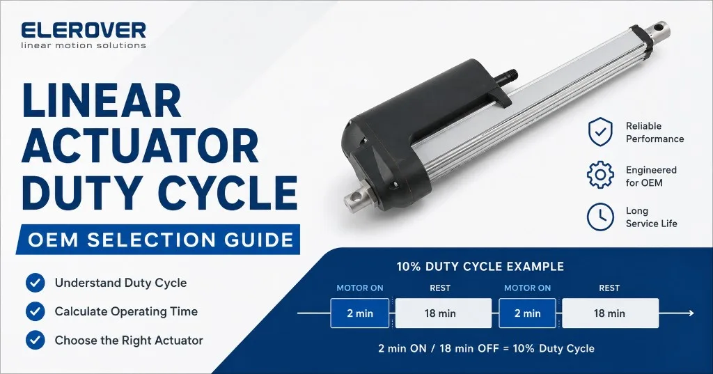
Force, stroke and speed are usually the first specifications an OEM buyer checks when selecting an electric linear actuator. But an actuator that can produce the required force is not automatically suitable for the required working cycle.
Duty cycle describes how long an actuator is intended to run relative to its rest period under specified operating conditions. It matters because the DC motor and drivetrain generate heat while moving.
For OEM equipment, ignoring duty cycle can lead to a common design mistake: choosing an actuator that meets load and stroke requirements on paper but is expected to operate more frequently than its published operating pattern allows.
Quick Answer: What Is Linear Actuator Duty Cycle?
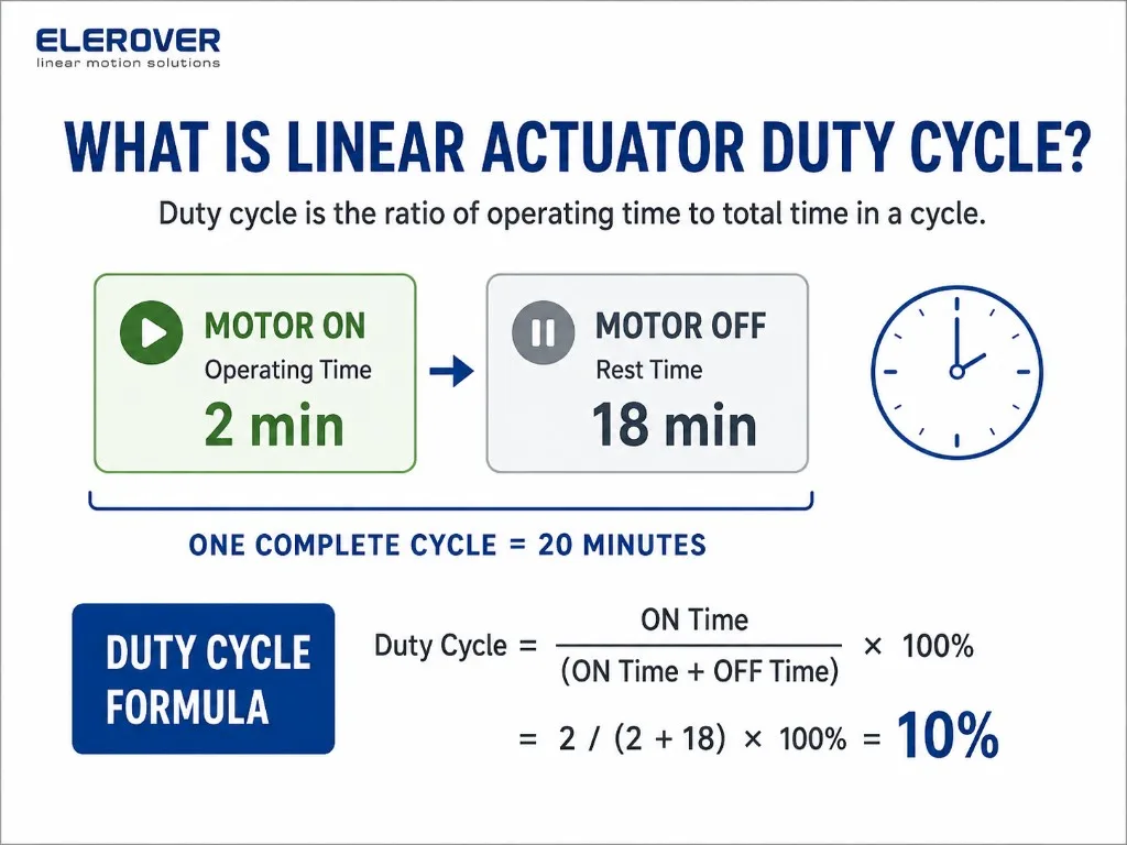
Linear actuator duty cycle is the relationship between operating time and total operating-plus-rest time.
A common percentage calculation is:
Duty Cycle (%) = ON Time / (ON Time + OFF Time) × 100
For example, an operating pattern of 2 minutes ON followed by 18 minutes OFF equals:
2 / (2 + 18) × 100 = 10%
However, a percentage alone does not always tell the complete story. Some actuator specifications use an S2 short-time duty description. Always follow the operating definition published for the exact actuator model and configuration.
Why Duty Cycle Matters to OEM Buyers
Electric actuators convert electrical energy into mechanical movement, while part of that energy becomes heat. The application therefore needs an appropriate operating/rest pattern.
Duty cycle matters in industrial lifting mechanisms, automated hatches, outdoor positioning systems, adjustable furniture, RV equipment, production fixtures, motorized pergolas and many other OEM products.
Two machines can require exactly the same force and stroke but need different actuator solutions if one moves twice per day and another repeatedly throughout a work shift.
Percentage Duty Cycle vs S2 Short-Time Duty
Percentage Duty Cycle
Elerover publishes a 10% duty cycle with a maximum 2 minutes continuous use for the SLA-12K heavy-duty linear actuator.
That tells an engineer both that the actuator is intended for intermittent operation and that the maximum continuous running period matters. The 10% figure should not be interpreted independently of the published continuous-use limit.
S2 Short-Time Duty
Some Elerover tubular actuator pages publish duty as S2 ≈ 2 min / 18 min. The SLA35M and SLA38M pages use this operating description.
When comparing models, do not assume different duty descriptions are interchangeable. Check the documentation for the exact actuator.
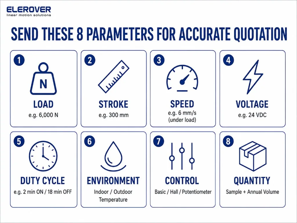
How to Calculate Required Actuator Running Time
First determine how long the motor must run during one machine operation.
A simple early-stage estimate is:
Travel Time = Stroke / Speed
Example: 300 mm Stroke at 6 mm/s
For a 300 mm stroke moving at an assumed 6 mm/s:
300 / 6 = 50 seconds
A full extension therefore takes approximately 50 seconds. If retraction requires the same time, one complete extend-and-retract operation requires approximately:
50 + 50 = 100 seconds
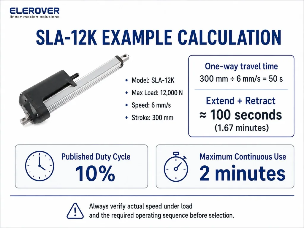
The final calculation should use speed under the project’s real load and selected configuration, not simply a no-load speed.
Cycles per Hour Are More Useful Than a Daily Average
Suppose a machine performs six complete operations per hour and each operation requires 100 seconds of motor running time.
6 × 100 = 600 seconds
That is 10 minutes of motor operation per hour, or a simple hourly average of about 16.7%.
But this does not prove that an actuator with a duty rating above 16.7% is suitable.
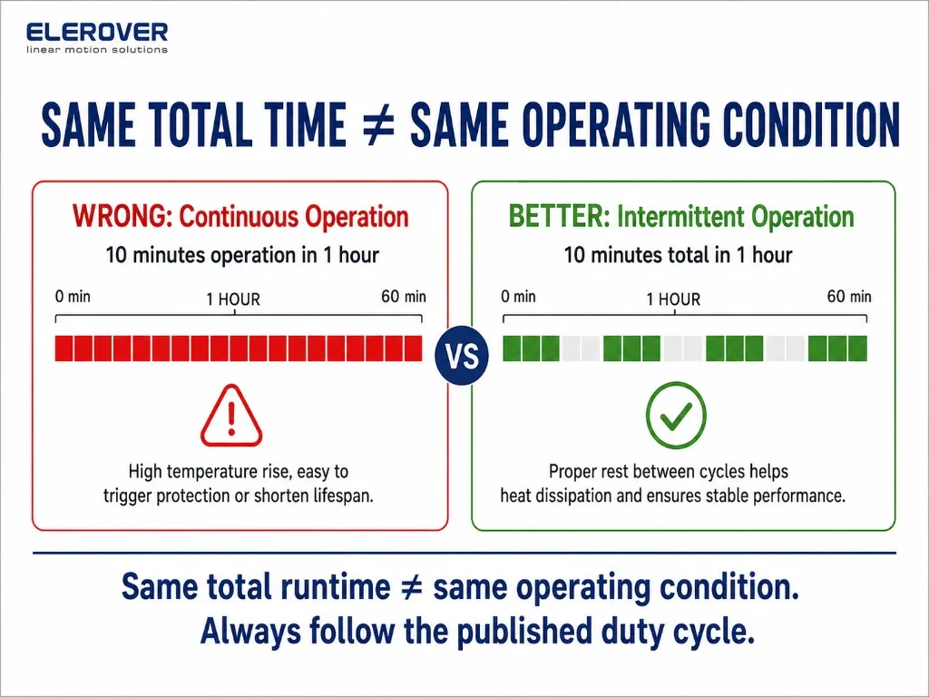
Six cycles spread evenly through an hour create a different operating pattern from six cycles performed consecutively. An RFQ should therefore state:
- total operations per hour;
- maximum consecutive cycles;
- maximum continuous running time;
- expected rest time between operations.
Duty Cycle Is Not the Same as Service Life
Duty cycle and service life describe different things.
Duty cycle concerns the operating/rest pattern.
Service life concerns expected operating life under defined conditions.
For example, the Elerover SLA-12K page publishes a 10% duty cycle, maximum 2 minutes continuous use, and an approximate service life of 25,000 cycles.
These values should not be turned into a universal lifetime prediction. Load, mounting, environment, stroke, speed and operating pattern can affect real system performance.
Load, Speed, Current and Duty Cycle Belong Together
A high-load application generally places greater demand on the motor than a lightly loaded mechanism.
For the SLA-12K, Elerover publishes:
- maximum load: 12,000 N at 6 mm/s;
- full-load current: 15–22 A at 12 V or 8–12 A at 24 V;
- duty cycle: 10%, maximum 2 minutes continuous use;
- IP66 protection.
These specifications show why force, speed, current and duty cycle should be reviewed together.
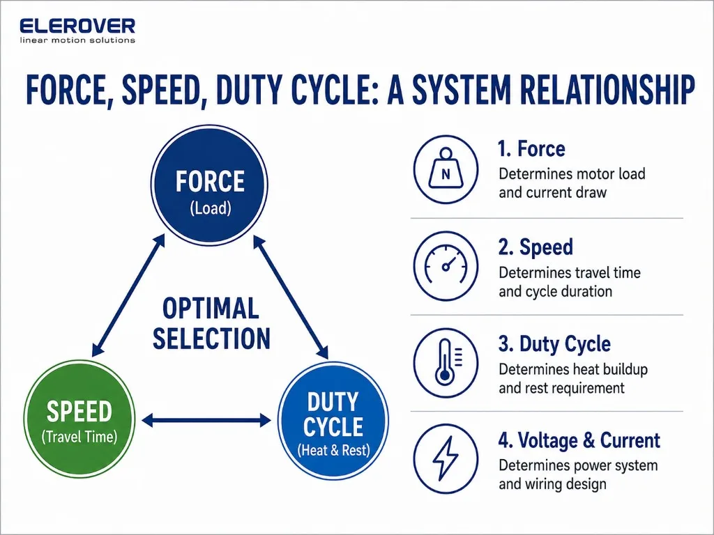
If your machine requires repeated high-load movement, send the complete operating sequence to the supplier before finalizing the actuator.
Duty Cycle and Power-Supply Sizing
Duty cycle does not replace current calculations. The power supply and controller still need to support actuator operating current.
For SLA-12K, Elerover publishes these recommended power-supply examples:
| System | Published Recommended Supply |
|---|---|
| 1 actuator at 12 V | 12 V / 30 A |
| 1 actuator at 24 V | 24 V / 15 A |
| 2 actuators at 12 V | 12 V / 50 A |
| 2 actuators at 24 V | 24 V / 25 A |
| 3–4 actuators at 12 V | 12 V / 100 A |
| 3–4 actuators at 24 V | 24 V / 50 A |
These recommendations are specific to SLA-12K and should not be copied to unrelated actuator models.
Why 24 V Is Worth Evaluating
Many industrial actuator families are available in both 12 V and 24 V configurations.
For SLA-12K, the published full-load current is 15–22 A at 12 V and 8–12 A at 24 V.
This does not mean 24 V is automatically better. The finished machine’s controller, battery or power supply, wiring and other electrical loads must also be considered. But if the electrical architecture is not yet locked, comparing both voltage options is useful.
Example 1: Heavy-Duty Industrial Lifting
Imagine an industrial mechanism requiring a 350 mm stroke, high push force and several movements during a work period.
The SLA-12K family is relevant to high-force applications, with published configurations up to 12,000 N at 6 mm/s and a 10% duty cycle with maximum 2-minute continuous use. See also the heavy-duty linear actuator guide for broader force-class context.
Before selection, calculate:
- actual force at the actuator mounting points;
- travel time in both directions;
- operations per hour;
- whether operations occur consecutively;
- power-supply and controller current;
- environmental and installation conditions.
The useful question is not simply, “Can this actuator lift the load?”
It is: “Can the actuator, controller and power supply perform the complete machine cycle under the required load?”
Example 2: Outdoor Tubular Motion
Elerover’s SLA38M tubular actuator page publishes:
- 12 V / 24 V DC;
- 20–500 mm stroke;
- up to 25 mm/s maximum speed;
- IP66 / IP67M protection;
- S2 ≈ 2 min / 18 min duty;
- up to 2300 N, depending on configuration.
A motorized shading system may move only when opening or closing. That intermittent operating pattern is fundamentally different from a continuously moving industrial process.
Application context therefore matters as much as headline force.
Example 3: Why Long Stroke Needs Extra Attention
The SLA-T50 page publishes 30–1000 mm stroke options and a 10% duty cycle. Its performance matrix includes:
- 5000 N at 2.4 mm/s;
- 3000 N at 4.2 mm/s;
- 1500 N at 7.69 mm/s.
A theoretical 1000 mm movement at 2.4 mm/s takes:
1000 / 2.4 ≈ 417 seconds
That is almost seven minutes.
This calculation immediately flags a need for engineering review against the published duty-cycle limits. Do not assume that every maximum stroke and performance-matrix combination is suitable for one uninterrupted full-stroke movement without confirmation.
Finding this issue before ordering samples can prevent a costly redesign.
Five Questions to Answer Before Selecting an Actuator
1. What Is the Real Load?
Calculate force from the mechanism geometry rather than using only the weight of the object. Lever arms and changing angles can alter actuator force significantly.
2. How Far Must It Move?
Define stroke and available retracted installation length.
3. How Fast Must It Move?
Specify required travel time or speed under working load.
4. How Often Will It Move?
Provide operations per hour, operations per day, maximum consecutive cycles and expected rest time.
5. What Is the Worst Operating Sequence?
Design around the most demanding realistic operating period, not only the daily average.
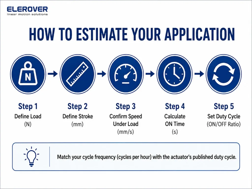
What Should an OEM Buyer Include in an RFQ?
A useful actuator RFQ should include:
- application or machine type;
- required push/pull force;
- stroke;
- desired speed under load;
- voltage;
- cycles per hour;
- maximum consecutive cycles;
- maximum continuous motor-running time;
- rest time between cycles;
- installation dimensions and mounting orientation;
- required IP rating;
- ambient operating conditions;
- feedback requirement;
- number of actuators operating together;
- controller requirement;
- prototype and estimated production quantity.
If possible, include a mechanism drawing showing actuator mounting points.
Common Duty-Cycle Selection Mistakes
Mistake 1: Looking Only at Maximum Force
Maximum force does not tell you whether the actuator is suitable for repeated operation.
Mistake 2: Using No-Load Speed for Cycle-Time Calculations
The machine operates under load. Use the relevant speed/load configuration.
Mistake 3: Averaging Operation Across an Entire Day
Ten minutes spread across eight hours is not equivalent to ten minutes of uninterrupted operation.
Mistake 4: Treating “10% Duty Cycle” as a Universal Rule
Duty definitions and continuous-running limits are model-specific.
Mistake 5: Selecting the Actuator Before Defining the Machine Cycle
Define the operating sequence before finalizing actuator, controller and power supply.
How to Choose the Right Elerover Actuator for Your Working Cycle
Start with the machine rather than the actuator catalog.
Document the mechanical load, stroke, required travel time and complete operating sequence. Then compare those requirements with the published force, speed, current, IP rating and duty-cycle data for candidate actuators in the linear actuator category.
For an OEM project, sending the operating profile before sample selection allows the actuator, controller and power system to be reviewed together.
Request an OEM Actuator Recommendation
If you are developing a new machine or replacing an existing actuator, contact Elerover with:
load + stroke + speed + voltage + cycles per hour + maximum continuous run time + installation dimensions + environment + quantity
A mechanism drawing is especially useful.
Elerover can then compare your requirements with its published actuator range and discuss an appropriate standard or project-specific configuration without relying on force rating alone.
FAQ
What does a 10% duty cycle mean for a linear actuator?
In percentage terms, it means operation for 10% of a defined operating-plus-rest period. The manufacturer's exact operating pattern and maximum continuous run time must also be followed.
Can a 10% duty-cycle actuator run continuously?
No. A 10% duty-cycle specification describes intermittent operation.
How do I calculate actuator travel time?
Use Travel Time = Stroke / Speed as an initial estimate, using speed relevant to the working load and configuration.
Does a higher-force actuator automatically have a better duty cycle?
No. Maximum force and duty cycle are separate specifications.
Does a 24 V actuator automatically have a better duty cycle than a 12 V actuator?
No. Voltage affects electrical architecture and current, but duty cycle must be confirmed for the exact actuator.
Is duty cycle the same as actuator lifespan?
No. Duty cycle describes an operating/rest pattern; service life describes expected operating life under defined conditions.
What should I send a supplier when asking about duty cycle?
Send load, stroke, required speed, voltage, cycles per hour, maximum consecutive cycles, rest period, mounting arrangement, environment and expected quantity.
المزيد من المقالات
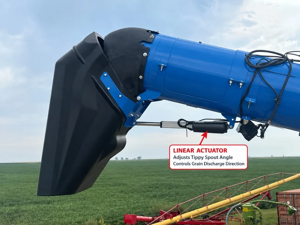
How an Electric Linear Actuator Adjusts an Unloading Auger Tippy Spout
Learn how an electric linear actuator can adjust an unloading auger tippy spout to improve grain discharge direction and trailer loading control.
قراءة المقال ←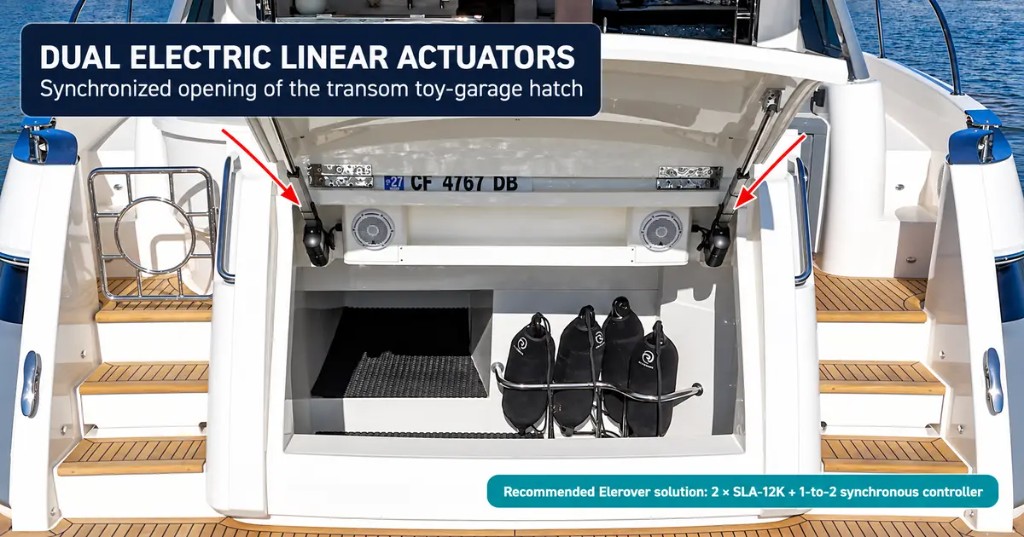
Dual Linear Actuators for Yacht Toy-Garage Hatches | SLA-12K
See how two synchronized electric linear actuators can open a yacht transom toy-garage hatch and how Elerover configures the SLA-12K system.
قراءة المقال ←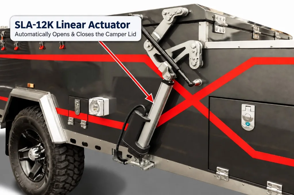
SLA-12K Linear Actuator for Automatic Camper Trailer Lids
See how a 12V or 24V SLA-12K heavy-duty linear actuator can automate the opening and closing of camper trailer lids and folding roof systems.
قراءة المقال ←