Linear Actuator and Slewing Drive for Solar Trackers
Learn how the Elerover SLA-15KB linear actuator and a slewing drive provide controlled tilt and rotation in single-axis and dual-axis solar tracking systems.
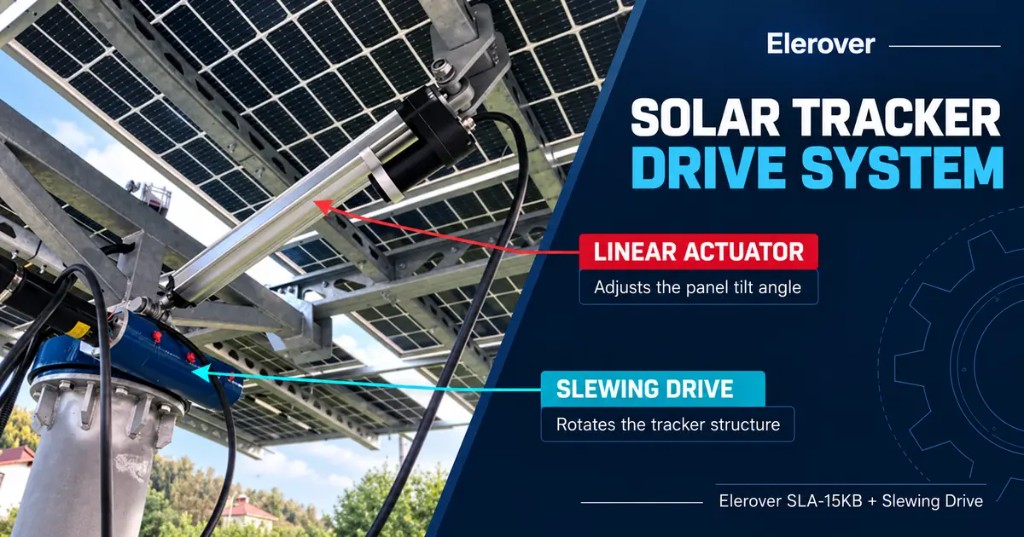
A solar tracking structure must move a large panel array slowly, accurately, and reliably. Depending on the tracker design, that movement may require one linear axis, one rotary axis, or a combination of both. An Elerover SLA-15KB linear actuator can provide the push-pull motion used to change panel tilt, while an Elerover slewing drive can provide controlled rotary motion around the tracker structure.
Used together in a dual-axis architecture, these two drive types separate the motion into two clear functions: the linear actuator adjusts elevation, and the slewing drive adjusts azimuth. This makes the system easier to control and allows each component to be selected for the load it handles.
What Does Each Drive Do in a Solar Tracker?
Although both products move the panel structure, they do not perform the same mechanical task.
SLA-15KB Linear Actuator: Panel Tilt or Elevation
The SLA-15KB converts the rotation of its electric motor into linear extension and retraction. When its mounting points are connected between the fixed support and the moving frame, a change in actuator length changes the panel tilt angle.
The actuator is suitable for applications that need:
- Controlled push-pull movement
- High axial force at low speed
- A defined stroke and repeatable end positions
- Position feedback for closed-loop tracking
- Self-locking behavior to help hold the mechanism when the motor stops
The actuator stroke cannot be selected from panel angle alone. The pivot locations, lever arm, closed length, open length, and required angular range must all be considered.
Slewing Drive: Tracker Rotation or Azimuth
A slewing drive produces high-ratio rotary movement. In a dual-axis solar tracker, it can rotate the tracker structure around a vertical or inclined axis to follow the sun from east to west. A worm gear design also provides compact speed reduction and high holding capacity.
The slewing drive is normally selected according to:
- Required output torque
- Static holding torque
- Tilting moment load
- Gear ratio and output speed
- Backlash or positioning requirement
- Mounting interface and available space
- Motor voltage and control method
The exact model should be calculated from the tracker structure and site loads rather than selected from panel area alone.
Single-Axis and Dual-Axis Configurations
The correct drive arrangement depends on the tracker geometry.
| Tracker configuration | Typical drive function | Suitable Elerover solution |
|---|---|---|
| Single-axis tilt tracker | Changes the angle around one pivot axis | SLA-15KB linear actuator |
| Single-axis rotary tracker | Rotates the array around one main axis | Slewing drive |
| Dual-axis tracker | Controls both elevation and azimuth | SLA-15KB plus slewing drive |
In a dual-axis system, the controller sends separate commands to the two drives. The linear actuator changes the elevation angle, while the slewing drive rotates the supporting structure. Hall sensor feedback from the actuator can help the controller monitor linear position. Rotary feedback can be added according to the slewing drive and control-system design.
SLA-15KB Specifications for Solar Tracking
The SLA-15KB is designed for high-load, low-speed linear motion. Available options allow the actuator to be matched to different tracker sizes and linkage geometries.
| Parameter | SLA-15KB options |
|---|---|
| Maximum load | 10,000 N, 12,000 N, or 15,000 N |
| Rated speed options | 1.4 mm/s, 2.0 mm/s, or 3.0 mm/s |
| Stroke range | 50-1,200 mm |
| Input voltage | 12 V DC or 24 V DC |
| Position feedback | Hall sensor |
| Limit control | Built-in or external magnetic limit switch |
| Dynamic protection rating | IP66 |
| Main materials | Aluminum housing and stainless-steel extension rod |
| Holding function | Integrated brake and strong self-locking design |
These values describe the available product range, not a universal solar tracker configuration. Actual thrust, speed, stroke, mounting dimensions, and duty cycle should be confirmed for each project.
Why Combine a Linear Actuator with a Slewing Drive?
Using a separate drive for each motion axis gives the designer several practical advantages.
1. Each mechanism handles the motion it is designed for
The SLA-15KB creates linear force efficiently, while the slewing drive handles rotary torque and overturning loads. This avoids forcing one mechanism to perform both tasks through a complicated linkage.
2. Low-speed movement is easier to control
Solar tracking does not require fast motion. It requires stable, incremental positioning. The slow actuator speeds and high reduction of a slewing drive are well suited to this operating pattern.
3. The two axes can be controlled independently
Elevation and azimuth can follow separate control commands. This supports scheduled tracking, light-sensor tracking, or a controller that combines both methods.
4. The system can hold position between adjustments
The SLA-15KB uses a brake and self-locking mechanism. A worm gear slewing drive also provides high holding capacity. The complete structure still requires an engineering check for wind, imbalance, shock loads, and emergency conditions.
How to Select the Correct SLA-15KB Stroke
Stroke is determined by the tracker linkage, not simply by the desired panel angle. Before selecting an actuator, define:
- The coordinates of both actuator mounting points
- The minimum and maximum panel angles
- The actuator length at each end position
- The shortest required retracted length
- The highest force throughout the full movement
- Clearance around the actuator, cable, and joints
The required stroke is the difference between the calculated extended and retracted installation lengths, with appropriate design allowance. Moving a mounting point closer to the pivot may reduce required stroke but can significantly increase actuator force. Moving it farther from the pivot may reduce force but require more travel and installation space.
How to Select the Slewing Drive
For the rotary axis, calculate operating torque and holding requirements under the most demanding design condition. The selection should include the array center of gravity, wind load, axis offset, support stiffness, dynamic factor, and required safety margin.
Key project values include:
| Selection input | Why it matters |
|---|---|
| Operating torque | Determines the torque required during tracking movement |
| Holding torque | Checks whether the drive can maintain position when stopped |
| Tilting moment | Accounts for overturning load on the rotary assembly |
| Required rotation range | Defines travel limits and cable-management needs |
| Output speed | Must match the tracker control strategy |
| Backlash | Influences positioning accuracy and movement under load reversal |
| Mounting dimensions | Ensures compatibility with the column and tracker frame |
Elerover supplies multiple slewing drive models for solar tracking and other rotary applications. Model selection should be based on the calculated loads and interface requirements.
Electrical and Control Integration
A typical system includes a 12 V DC or 24 V DC power supply, tracker controller, actuator feedback input, motor reversing outputs, and travel-limit protection. For a two-axis tracker, each motor needs an independently controlled channel.
The controller should prevent movement beyond the mechanical range and provide a safe response to sensor faults, power interruption, or abnormal current. The structural design should also use mechanical stops where required. The actuator’s Hall signal can provide relative position information, but the final control architecture depends on the required positioning accuracy and homing method.
Information Needed for an Application Review
To recommend a suitable actuator configuration and slewing drive, please provide:
- Panel dimensions, quantity, and total moving mass
- Tracker drawing with pivot and mounting-point locations
- Required elevation and azimuth ranges
- Design wind speed and calculated wind loads
- Required linear force, rotary torque, holding torque, and tilting moment, if available
- Target tracking speed and daily operating cycles
- Power supply voltage and controller signal type
- Ambient temperature and installation conditions
- Prototype quantity and expected annual volume
One important distinction is that 15,000 N is linear actuator force, not the allowable weight of the complete solar array. The actual actuator load changes with linkage geometry and panel angle. Likewise, slewing drive capacity must be checked using torque and moment loads, not only the structure’s mass.
A Practical Drive Package for Solar Tracker OEMs
For a dual-axis tracker, a practical starting architecture is:
- One SLA-15KB linear actuator for elevation adjustment
- One correctly sized Elerover slewing drive for azimuth rotation
- Independent motor-control outputs for both axes
- Position feedback and calibrated travel limits
- Mechanical interfaces designed around the calculated load cases
This arrangement combines high-force linear positioning with compact rotary movement in one coordinated system. Elerover can support actuator stroke selection, feedback options, cable requirements, and slewing drive matching for prototype and production projects.
Frequently Asked Questions
Can the linear actuator replace the slewing drive?
Not directly. A linear actuator creates push-pull motion, while a slewing drive creates rotary motion. A linkage can convert linear travel into rotation around one pivot, but continuous or wide-range azimuth rotation normally requires a rotary solution.
Can the SLA-15KB be used in a single-axis tracker?
Yes. If the tracker geometry uses a linear linkage to rotate one axis, the SLA-15KB can provide the required extension and retraction after force and stroke calculations are completed.
Why is Hall sensor feedback useful?
Hall pulses allow the controller to monitor actuator movement and estimate position. They can support repeatable tracking, synchronization logic, and fault detection when correctly integrated and calibrated.
Which slewing drive model should I choose?
The image alone is not enough to identify the correct size. Output torque, holding torque, tilting moment, gear ratio, backlash, mounting dimensions, and site loads must be reviewed before a model is selected.
Discuss Your Solar Tracker Drive Requirements
Need a coordinated linear and rotary drive solution? Review the SLA-15KB linear actuator and our slewing drive range, then contact Elerover with your tracker drawing and load data. We can help define the actuator stroke, force option, feedback configuration, and slewing drive selection for your project.
FAQ
Can the linear actuator replace the slewing drive?
Not directly. A linear actuator creates push-pull motion, while a slewing drive creates rotary motion. A linkage can convert linear travel into rotation around one pivot, but continuous or wide-range azimuth rotation normally requires a rotary solution.
Can the SLA-15KB be used in a single-axis tracker?
Yes. If the tracker geometry uses a linear linkage to rotate one axis, the SLA-15KB can provide the required extension and retraction after force and stroke calculations are completed.
Why is Hall sensor feedback useful?
Hall pulses allow the controller to monitor actuator movement and estimate position. They can support repeatable tracking, synchronization logic, and fault detection when correctly integrated and calibrated.
Which slewing drive model should I choose?
The image alone is not enough to identify the correct size. Output torque, holding torque, tilting moment, gear ratio, backlash, mounting dimensions, and site loads must be reviewed before a model is selected.
المزيد من المقالات
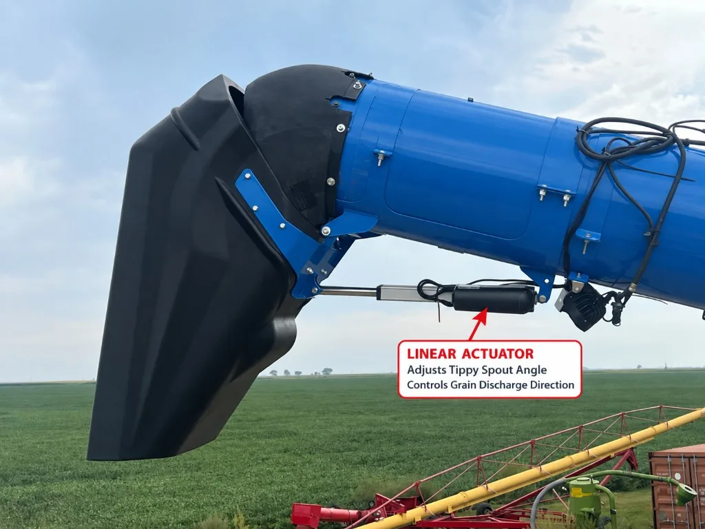
How an Electric Linear Actuator Adjusts an Unloading Auger Tippy Spout
Learn how an electric linear actuator can adjust an unloading auger tippy spout to improve grain discharge direction and trailer loading control.
قراءة المقال ←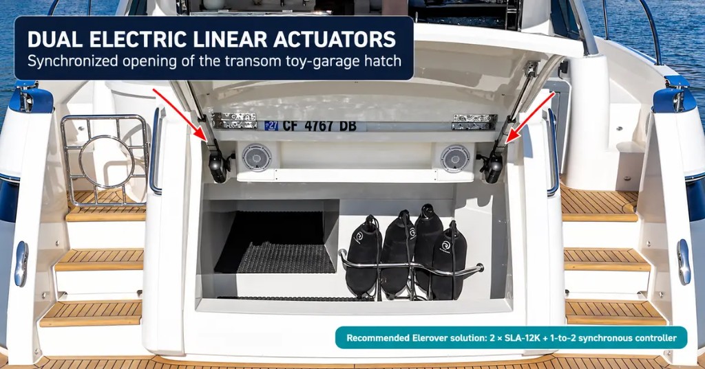
Dual Linear Actuators for Yacht Toy-Garage Hatches | SLA-12K
See how two synchronized electric linear actuators can open a yacht transom toy-garage hatch and how Elerover configures the SLA-12K system.
قراءة المقال ←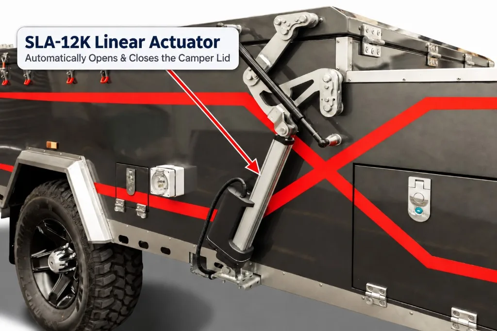
SLA-12K Linear Actuator for Automatic Camper Trailer Lids
See how a 12V or 24V SLA-12K heavy-duty linear actuator can automate the opening and closing of camper trailer lids and folding roof systems.
قراءة المقال ←