12V vs 24V Linear Actuator
OEM comparison of 12V and 24V DC electric linear actuators—current draw, cable sizing, noise, controllers and when each voltage wins for industrial projects.
· Elerover manufacturer guide
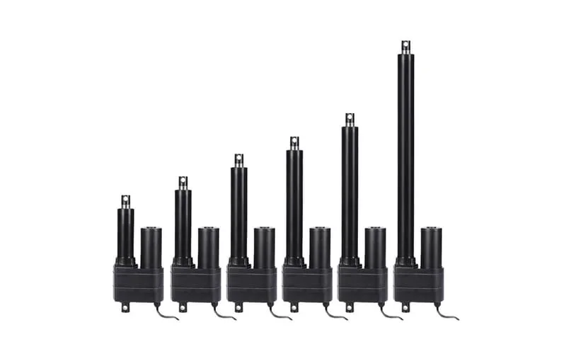
Voltage is one of the first electrical decisions in an OEM linear actuator project—and one of the easiest to get wrong. Choose poorly and you inherit thick cables, excessive voltage drop, hot connectors, nuisance trips or an incompatible controller. This guide compares 12V DC and 24V DC electric linear actuators from a manufacturer’s perspective, using the practical trade-offs Elerover sees across furniture, industrial, agricultural and vehicle-adjacent programs.
Elerover supplies electric linear actuators predominantly in 12V and 24V, with selected platforms offering additional voltages. Browse the live Linear Actuator category for Working Voltage options on each model. The product specification table—not the marketing title—is authoritative.
Why voltage matters more than “preference”
For a given mechanical power, electrical power is roughly P ≈ V × I. Halving the voltage roughly doubles the current for the same power. Higher current means:
- Larger cable cross-section to control voltage drop and heating
- Higher I²R losses in connectors and harnesses
- Greater stress on switches, relays and MOSFETs
- More sensitivity to contact resistance over the product lifetime
That is why industrial cabinets and longer cable runs often standardize on 24V, while battery and automotive-adjacent platforms often stay on 12V because the vehicle bus already exists.
Quick comparison: 12V vs 24V
| Factor | 12V DC | 24V DC |
|---|---|---|
| Current for same power | Higher | Lower |
| Cable voltage drop | More sensitive on long runs | More tolerant for the same cable |
| Battery / mobile OEM | Very common | Common on industrial 24V systems |
| Controller ecosystem | Wide in furniture & mobility | Wide in industrial automation |
| Heat in wiring | Higher for same power | Lower for same power |
| Typical Elerover use | Compact OEM, vehicles, short runs | Industrial machines, longer harnesses |
Neither column is “better” in absolute terms. The winning voltage is the one that matches your power architecture with acceptable current and drop.
Technical explanation: current, drop and stall
Running current vs stall current
Datasheets often emphasize running current under rated load. Controllers and fuses must also survive stall or near-stall current when the mechanism jams or hits a hard stop. When you request a quote from Elerover, include cable length and whether soft-start or current limiting exists in the controller.
Voltage drop estimate (practical)
Voltage drop rises with current and cable length and falls with conductor cross-section. On a long 12V run, a few volts of drop can push the actuator below its effective operating window, reducing speed and force. Symptoms include sluggish travel at end of stroke, controllers that brown out, or intermittent resets.
OEM rule of thumb: if your harness is long and the actuator is high-force (high current), prefer 24V or thicken the cable—and verify both.
Noise and EMC
Higher current switching can increase conducted and radiated noise. Good practice includes short power loops, proper grounding, and controller placement near the actuators when practical. Multi-actuator systems should treat power distribution as a designed bus, not daisy-chained leftovers.
Selection criteria: which voltage should you lock?
Use this decision sequence:
- What supply already exists? Vehicle 12V, industrial 24V cabinet, custom PSU—start there.
- How long is the cable? Longer → favor 24V or larger conductors.
- What is the force class? Higher force → higher current → voltage choice becomes critical.
- Is there a controller family already chosen? Actuator voltage must match the controller output.
- Is the system battery-powered? Runtime and peak current may dominate over industrial norms.
- Confirm Working Voltage on the product page before releasing drawings.
Also decide early whether you need hall feedback and synchronization—those affect controller selection as much as voltage. See How to choose a linear actuator for the full mechanical checklist.
Comparison by OEM scenario
| Scenario | Prefer | Why |
|---|---|---|
| Passenger vehicle accessory / 12V battery OEM | 12V | Matches existing bus |
| Industrial machine with 24V control power | 24V | Lower current, cleaner panel design |
| Two synchronized recliner actuators, short cables | 12V or 24V | Either works if controller matches; many furniture platforms use 24V |
| High-force hatch, 8–12 kN, 5+ m cable | 24V (typical) | Current and drop become painful at 12V |
| Solar / outdoor industrial assist | Often 24V | Aligns with industrial supplies; confirm model |
| Compact robot / lab mechanism near PSU | Either | Short cable reduces drop; pick supply convenience |
Engineering examples
Example 1 — Compact OEM on 12V
A robotics accessory needs ~100–200 N, short leads, existing 12V rail.
Path: Linear Actuator → SLA-T01 series → SLA-T01 linear actuator for robot. Confirm the listed Working Voltage options on that product page before ordering.
Example 2 — Gate / latch industrial mid-force
A gate latch mechanism needs mid-force travel, 12V or 24V available.
Path: Category → SLA03 6000N series → SLA03 100mm gate latch model. Choose the voltage that matches the panel supply; do not mix actuator and controller voltages.
Example 3 — Construction / outdoor industrial, dual voltage platform
An outdoor mechanism needs roughly 8,000 N class force with documented 12V/24V options.
Path: Category → SLA08 8000N → SLA08 100mm construction machinery model. For long outdoor cable runs, 24V is usually the cleaner electrical design.
Example 4 — Heavy-duty hatch
A vehicle or equipment hatch needs ~12,000 N class force.
Path: Category → SLA-12K 12000N series → SLA-12K heavy-duty DC actuator. Verify voltage, current and Protection Class together—force alone is not enough. See also the heavy-duty guide.
Controllers and multi-actuator systems
Voltage selection is a system decision:
- Actuator Working Voltage
- Controller output voltage
- Power supply continuous and peak current
- Cable gauge and length
- Feedback wiring (hall / potentiometer) when used
Browse controllers when two or more actuators must travel together. Mismatched voltage between actuator and controller is a common RFQ correction—catch it in design review.
Applications
- Furniture OEM: often 24V for harness simplicity; some 12V lines remain
- Medical / care equipment: voltage follows the certified power architecture
- Agriculture: outdoor IP plus 12V/24V industrial supplies—confirm both
- Solar assists: frequently 24V industrial; verify stroke model ratings
- Mobile / vehicle: 12V common; watch cable length to rear hatches
- Factory automation: 24V control power is the default in many plants
For environment and sealing, combine this guide with IP65 vs IP68. For force sizing, use force calculation.
Recommended Elerover product path
- Category: Linear Actuator
- Series: SLA-T01, SLA03, SLA08, SLA-12K
- Products: open the stroke-specific model and read Working Voltage, current-related notes and Max Load
- Controllers: Controller category when synchronizing
- Contact: Contact Elerover with voltage, cable length, force, stroke and quantity
Power supply and protection design
Treat the power stage as part of the actuator system:
- Continuous current rating of the PSU must exceed running current with margin
- Peak capability must survive stall or inrush, or the controller must current-limit safely
- Fusing should protect wiring without nuisance-tripping on normal starts
- Soft-start / ramping in controllers reduces mechanical shock and peak demand
- Isolation and grounding practices matter more as cable length and current rise
If your team is migrating a 12V design to 24V, redesign the harness and protection devices—do not only swap the actuator nameplate voltage.
Voltage drop worked example (illustrative)
Suppose a high-force actuator draws a demanding current on a long harness. At 12V, a 1.5 V drop is already a large fraction of the supply; at 24V, the same drop is a smaller percentage of the rail. That is why OEMs often report “it worked on the bench” (short leads) and “fails on the machine” (long loom). Always validate:
- Bench current at rated load
- Machine current with production cable length
- Voltage at the actuator connector under load—not only at the PSU terminals
Share those measurements with Elerover if the motion looks underpowered after installation.
Battery systems and duty
On battery platforms, voltage sag under load can mimic an undersized actuator. Check:
- Battery state of charge during worst-case moves
- Parallel loads that dip the bus when the actuator starts
- Wire resistance from battery to actuator
- Whether 24V conversion is justified by cable length and peak current
Runtime calculations should use realistic loaded current, not no-load brochure values.
Failure modes tied to voltage mistakes
| Mistake | Typical symptom | Fix |
|---|---|---|
| Long thin 12V cable | Slow travel, brownouts | Thicken cable or move to 24V |
| Actuator 24V / controller 12V | No motion or damage risk | Match system voltage |
| Ignoring stall current | Tripped breakers, MOSFET stress | Upsize supply/protection or limit current |
| Operating above rated voltage | Overheating, shortened life | Stay within Working Voltage |
| Dual-voltage assumption without datasheet | Wrong spare parts | Read each SKU’s Working Voltage |
RFQ electrical checklist
When you contact Elerover, include:
- Selected or candidate series/product URLs
- Desired Working Voltage
- Cable length one-way and conductor size if known
- PSU or battery description
- Controller model constraints
- Number of actuators on the same supply
- Peak vs continuous expectations
Use Contact and reference this guide so the factory response can address electrical integration, not only Max Load.
How this guide connects to other resources
- Overall selection: How to choose a linear actuator
- Force sizing: How to calculate linear actuator force
- Environment: IP65 vs IP68 linear actuator
- High force current budgets: Heavy duty linear actuator guide
- Catalog entry: Linear Actuator category
Manufacturer guidance
Elerover’s factory recommendation always starts from the published Working Voltage on the selected model. If your project needs a voltage variant listed as available on a platform, request OEM confirmation with annual volume. Do not operate actuators outside the rated voltage window to “get more speed”—that is a reliability risk, not a tuning method.
When you are ready, open the category, shortlist a series, pick a product page, then send the electrical diagram with cable lengths. That is the fastest path from RFQ to a manufacturable BOM.
FAQ
Is 24V always better than 12V for linear actuators?
Not always. 24V usually lowers current for the same power and helps with longer cables, but 12V remains common for battery systems and many mobile OEM platforms. Choose based on available supply, cable length and current budget.
Can the same actuator model run on both 12V and 24V?
Many Elerover platforms list both 12V and 24V options. Always confirm the Working Voltage field on the specific product page—do not assume dual-voltage unless it is specified.
Does voltage change the force rating?
Force is defined by the mechanical and motor design at the rated voltage. Running outside the specified voltage can reduce performance or damage the motor. Use the rated voltage from the specifications table.
How do I estimate cable size for a 12V actuator?
Size for stall or inrush current, not only running current, and keep voltage drop within your control tolerance over the full cable length. Longer 12V runs often need thicker cable or a move to 24V.
Which voltage is better for multi-actuator furniture systems?
Both exist in the market. Many furniture OEM platforms use 24V for lower current and cleaner wiring; some remain on 12V. Match the actuator voltage to the controller and power supply as a system.
Can Elerover supply non-standard voltages?
Selected platforms list additional voltages beyond 12V/24V. Request OEM confirmation with load, stroke and annual volume via Contact before freezing a non-standard electrical design.
More OEM guides
- Heavy Duty Linear Actuator Guide OEM guide to heavy-duty electric linear actuators—force classes from 6,000N to 12,000N+, IP ratings, outdoor duty and Elerover high-force series recommendations.
- How to Calculate Linear Actuator Force OEM method to calculate electric linear actuator force—static load, friction, angle, dynamics and safety factor—mapped to Elerover force classes and series.
- How to Choose a Linear Actuator OEM buyer guide to choosing an electric linear actuator—force, stroke, voltage, IP rating, duty cycle, feedback and mounting—with Elerover series recommendations.
- IP65 vs IP68 Linear Actuator OEM guide to IP65 vs IP68 (and nearby ratings) for electric linear actuators—dust, water, outdoor duty—and how to read Elerover Protection Class specs.